


Overview
According to the statistics, 80% of fire accidents in China are building fire, while electrical fault is the primary cause of building fire. The electrical fire is mainly caused by short circuit, leakage current, overload of circuit breaker or line and other faults. In this case, timely and effective monitoring on electrical fire hazards caused by leakage of distribution line is necessary for preventing the frequent occurrence of electrical fire.
Code for Fire Protection Design of Buildings (GB 50016-2014) defines the requirements for buildings or sites in which the electrical fire monitoring system shall be installed. Electrical Fire Monitoring System (GB14287-2014) has been formally implemented since June 1, 2016, and provides new requirements and standards for electrical fire monitoring equipment, residual current detector for electrical fire monitoring, temperature detector for electrical fire monitoring and other devices. With increasing focus of country and units concerned, the public have strengthened their knowledge on importance of electrical fire prevention, and the electrical fire monitoring system, as an early pre-alarm system, has been increasingly applied in the intelligent buildings.
Reference Standards
Code for Fire Protection Design of Buildings (GB 50016-2014)
Code for Design of Automatic Fire Alarm System (GB 50116-2013)
Electrical Fire Monitoring System (GB 14287-2014)
General Technical Requirements for Fire Control Center (GB 25506-2010)
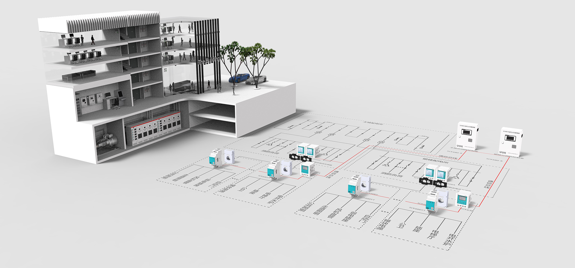
Composition of Electrical Fire Monitoring System
In large building or residential area, the incoming line of power supply is mainly at a voltage class of 10 kV. The electric energy is delivered to high-voltage distribution substation first and then distributed to each terminal substation by the high-voltage distribution substation. 10kV high voltage is reduced to the voltage (220/380V) required for general electric equipment through a distribution transformer, and then distributed to electric equipment through low-voltage distribution line.
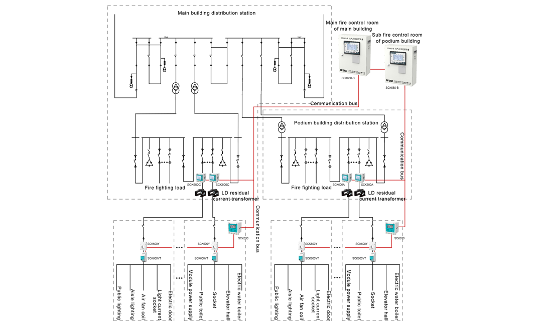
Fire control room should be set on the first floor or ground floor of building and close to the exterior wall, with electrical fire monitoring equipment installed in it. When two or more than two fire control rooms are set, master control room and sub-control room for fire protection shall be identified, and the electrical fire monitoring equipment in the master control room shall display the information of that in the sub-control room.
Residual current detector for electrical fire monitoring should be set at the outlet terminal of first-level distribution cabinet (box), but should not be set on the distribution line of IT system and fire protection system). When the leakage current of power supply line is greater than 500 mA, the detector shall be set on the distribution cabinet (box) of next level.
The temperature detector for electrical fire monitoring should be installed on the cable joint, cable body, switch or other heat-producing parts in contact with or close to the protection targets.
Monitoring Function
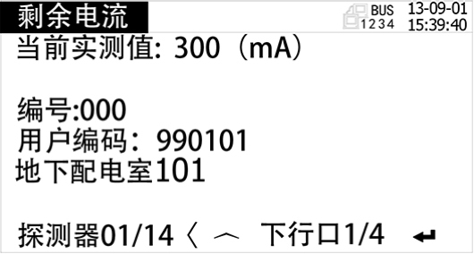
 Real-time monitoring
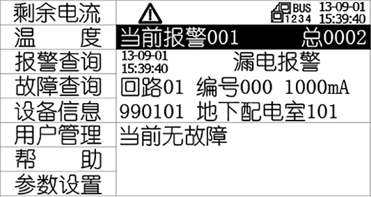
The system monitors real-time residual current and temperature of each circuit, and displays specific description and number of circuit and various function buttons on main interface.
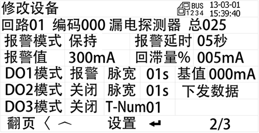
 Alarm setting and reminding
The system supports remote setting of alarm values for residual current and temperature and setting of various circuit information and status. In case of circuit alarm, the system will send sound-light alarm signal and conduct event recording in sequence.
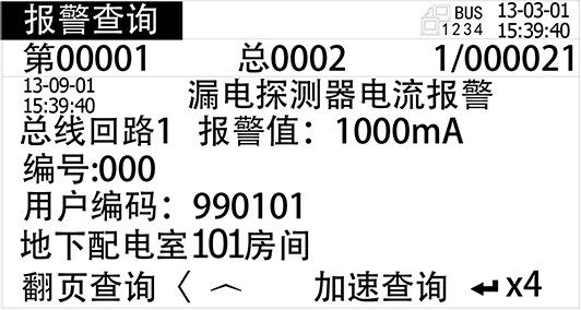
 Alarm and fault recording
The monitoring equipment automatically records the off-limit alarms and equipment faults, and all the records may be accessed through alarm and fault inquiry. If there are too many records and the historical information is no longer needed, the historical records of equipment may be cleared by setting in the “Parameter Setting”. (Note: Advanced permission is required for clearing)
 Display of status information
The main interface displays the current alarm in real time, and status lamp on the panel indicates the current system status.
 User level management
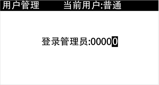
The monitoring equipment system provides two-level permissions (general permission and advanced permission). The default user is divided into operator (with general permission) and administrator (with advanced permission). The administrator permissions are logged in and out on the “User Management” menu
 System operating information
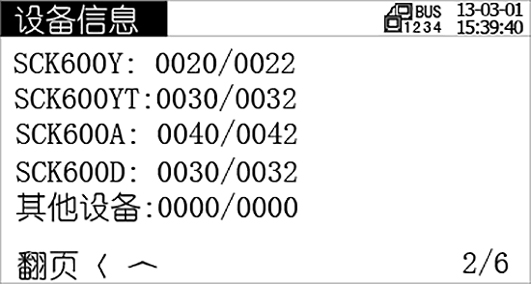
Detector information (on-line number and total number of leakage and temperature detectors of each circuit) can be inquired on the equipment information menu.
Distribution Cabinet Scheme
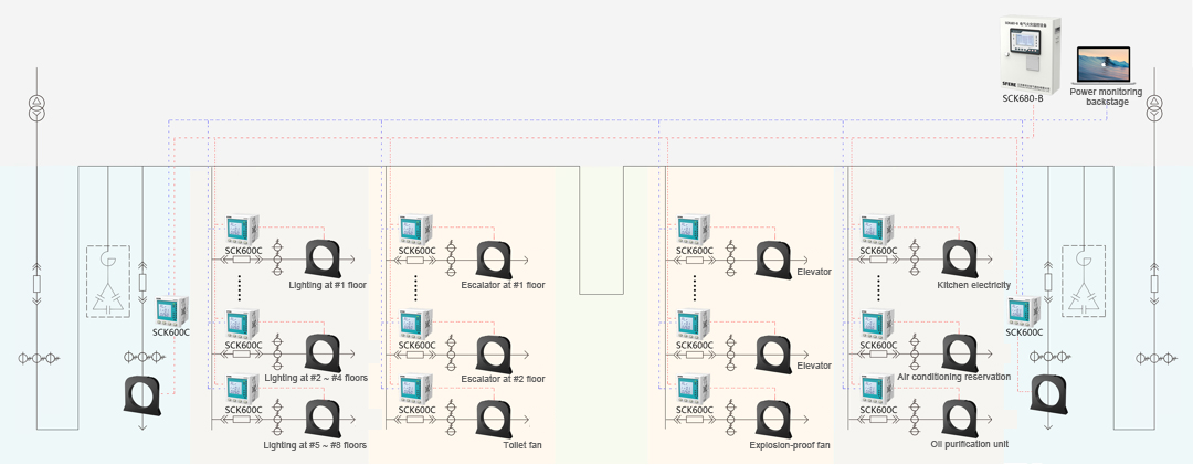
Electrical fire monitoring & Power monitoringOne LD series residual current transformer and NTC temperature sensor as well as one SCK600C detector for electrical fire monitoring shall be installed on each circuit of feeder cabinet.
SCK600C multi-function detector for electrical fire monitoring can monitor one-circuit residual current and four-circuit temperature as well as real-time electric parameters of circuit such as three-phase voltage, current, power, frequency, power factor, harmonic and bidirectional electric energy. The detector is provided with two communication interfaces, which can upload data respectively to electrical fire monitoring equipment and electric power monitoring background for separate display of data. In addition, when the electric power monitoring software is integrated with the function of electrical fire monitoring, the interfaces can upload the electrical fire parameters together with the electric parameters to the electric power monitoring background, to realize the function of both electrical fire monitoring and electric power monitoring. In this case, installation of additional multi-function instruments is avoided to save the space and reduce the cost.
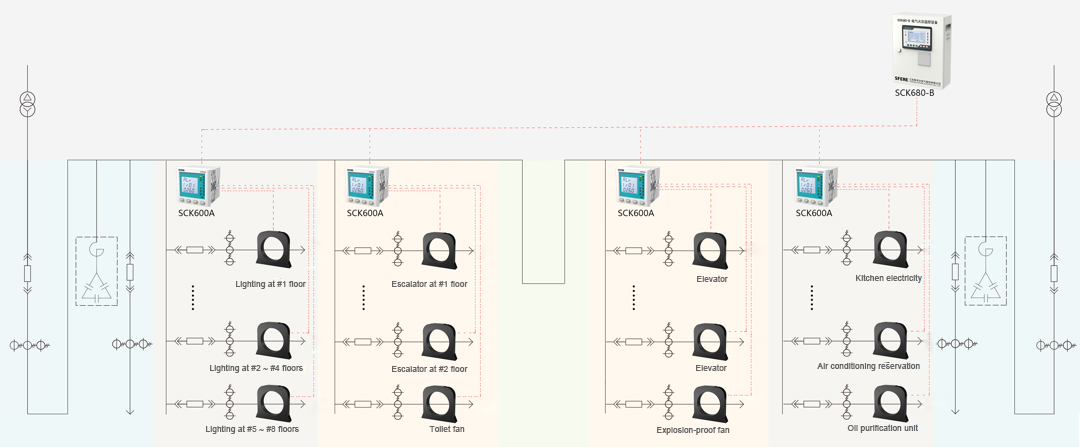
One LD series residual current transformer and NTC temperature sensor shall be installed on each circuit of feeder cabinet, and one SCK600A series detector for electrical fire monitoring shall be installed on each cabinet
SCK600A series multi-circuit detector for electrical fire monitoring can monitor at most 16 circuits. Each feeder cabinet can realize real-time monitoring on residual current and temperature of its circuits as well as local display and off-limit alarm with only one SCK600A series detector, so as to save the space and reduce the cost. In addition, SCK600A detector may be provided with RS485 interface or two-line interface for fire control, to adapt to different site conditions and superior equipment
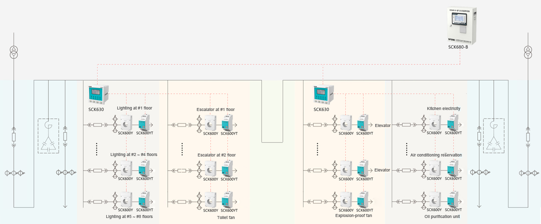
One SCK600Y residual current detector for electrical fire monitoring, SCK600YT temperature detector for electrical fire monitoring and NTC temperature sensor shall be installed on each circuit of feeder cabinet. One row of distribution cabinets or multiple distribution cabinets shall be provided with one SCK630 monitoring unit
SCK600Y residual current detector for electrical fire monitoring and SCK600YT temperature detector for electrical fire monitoring are of integrated structure, and their installation is of guide rail type with small space. The method of non-polar two-wire connection and bus power supply is adopted, to avoid connection of additional power supply and simplify the wiring. As these detectors are installed in different positions and separately set up, they are featured by flexible installation and easy maintenance in future. One SCK630 monitoring unit can connect 32 monitoring points at most, to realize local real-time monitoring and off-limit alarm on the residual current and temperature of feeder circuits. In addition, the function of bus isolation can be realized to prevent influence on other parts when part of bus fails, and the data can be uploaded to the electrical fire monitoring equipment through communication
Distribution Box Scheme
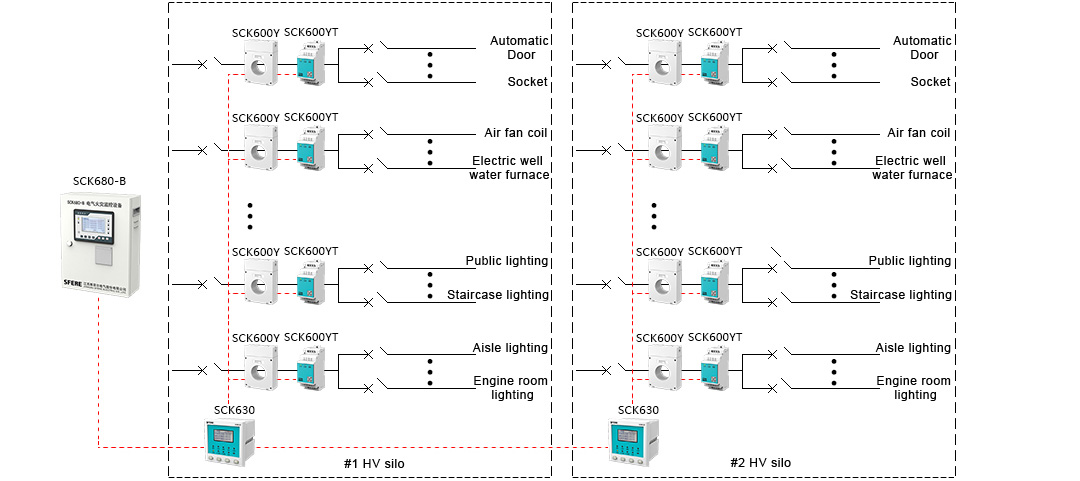
Regional monitoring schemeWhen the leakage current of power supply line is greater than 500 mA, the electrical fire monitoring detector shall be set on the distribution box of next level. One SCK600Y integrated electrical fire monitoring detector, SCK600YT temperature detector for electrical fire monitoring and NTC temperature sensor may be installed in each distribution box. One floor or one electrical riser shall be provided with a SCK630 monitoring unit
Two-line communication is adopted for SCK600Y residual current detector and SCK600YT temperature detector. The method of star connection and ring connection as well as the power supply of bus are adopted without connection of additional power supply. In this case, large amount of wires can be saved to realize economic and convenient wiring on each floor. SCK630 monitoring unit may be installed on the first floor of building or positions easy for observation, to realize local monitoring and off-limit alarm in small area. In addition, the unit can supply the power to its connected detectors, extend the communication distance, and isolate the bus to prevent influence on other parts when part of bus fails. The data can be uploaded to the electrical fire monitoring equipment through communication
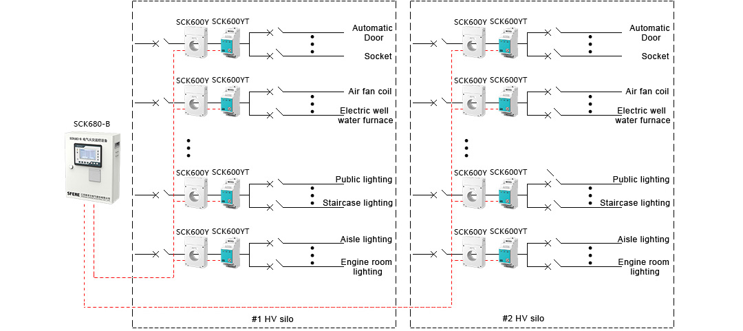
One SCK600Y residual current detector, SCK600YT temperature detector and NTC temperature sensor shall be installed in each distribution box. The communication line ofSCK600Y residual current detector and SCK600YT temperature detector shall be directly connected to the electrical fire monitoring equipment
SCK600Y residual current detector and SCK600YT temperature detector are of integrated structure, and their installation is of guide rail type with small space, which is suitable to the distribution box with limited space. The detectors communicate via two-line buses. The method of star connection and ring connection as well as the power supply of bus are adopted without connection of additional power supply. In this case, large amount of wires can be saved during the wiring of each floor. As the detectors are directly connected to the host, the minimum number of equipment is used. They are the most economical, and featured by small floor area and less monitoring points. In addition, the data can be viewed from the monitoring equipment in the fire control room instead of examination on the site
Product Introduction
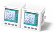
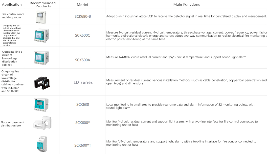
Electrical fire monitoring equipment
SCK680-B
Features
☑Adopt 5-Inch industrial graphic lattice LCDFunction
☑ Monitoring alarm, fault alarm, self-inspection, information display and inquiryApplication
☑ Fire control room and duty room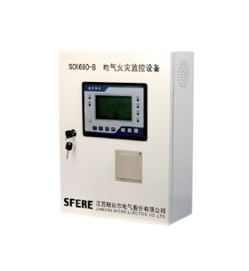
Electrical fire monitoring detector
SCK600C
Feature
☑ Provide protection against residual current, temperature, overcurrent, overvoltage, open phase, harmonic excess, fire control linkage and so onFunction
☑ Measure the electrical fire and electric power parameters (such as electric energy and harmonic); support two-way communication; and connect to the electrical fire monitoring equipment and the electric power monitoring background at the same timeApplication
☑ Outgoing line circuit of low-voltage distribution cabinet for which the acquisition of electrical fire and electric power parameters is required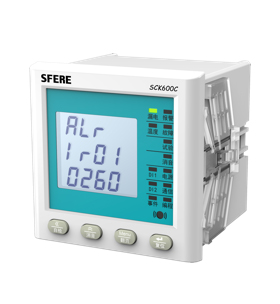
Electrical fire monitoring detector
SCK600A
Features
☑ Provide protection against residual current, temperature and so onFunction
☑ Monitoring, alarm and communicationApplication
☑ Outgoing line of low-voltage distribution cabinet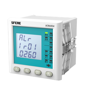
Residual current transformer
LD
Features
☑ Measuring range: 50~1000mAFunction
☑ Measure the residual current and combine with SCK600A and SCK600CApplication
☑ Outgoing line circuit of low-voltage distribution cabinet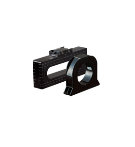
Electrical fire monitoring unit
SCK630
Features
☑ Adopt industrial graphic lattice LCDFunction
☑ Monitoring, alarm and communication in small areaApplication
☑ Outgoing line circuit of low-voltage distribution cabinet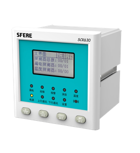
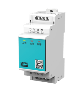
Residual current detector for electrical fire monitoring
SCK600Y
Features
☑ Adopt non-polar two-wire connection and power supply of bus for simple and convenient wiring on the siteFunction
☑ Measure the residual current, and upload the data to monitoring unit or hostApplication
☑ Outgoing line circuit of low-voltage distribution cabinet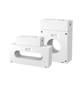
Temperature detector for electrical fire monitoring
SCK600YT
Features
☑ Adopt non-polar two-wire connection and power supply of bus for simple and convenient wiring on the siteFunction
☑ Measure the temperature, and upload the data to monitoring unit or hostApplication
☑ Cable joint on outgoing line circuit of low-voltage distribution cabinet